In a note on how we looked for cracks nobody can see I gave eddy current testing one paragraph. It is the method with the neatest physics of the lot, and the physics is what decides where it works.
This note works it through with numbers, for the aluminium most small aircraft are made of.
What the coil does
The probe is a small coil driven with alternating current. That current makes a magnetic field that changes direction thousands or millions of times a second.
Hold the coil against a conductor and the changing field induces currents in the metal, flowing in closed loops parallel to the surface. These are the eddy currents. By Lenz's law they make a field of their own that opposes the coil's, and the coil feels that as a change in its impedance: how much it resists the alternating current driving it.
A crack is a gap the eddy currents cannot cross. They have to go around it, the opposing field changes, and so does the coil's impedance. The instrument shows that change. Nothing touches the inside of the part, nothing is painted on it, and nothing is left behind.
Skin depth: how far down it sees
Eddy currents are strongest at the surface and fade with depth. The current density at depth x is J(x) = J₀ · e^(−x/δ), where δ is the standard depth of penetration, or skin depth:
δ = 1 / √(π · f · μ · σ)
Here f is the test frequency, μ is the magnetic permeability of the metal and σ its electrical conductivity. Aluminium is not magnetic, so μ is that of free space, 4π × 10⁻⁷ H/m.
Conductivity in this field is usually quoted as a percentage of the International Annealed Copper Standard, where 100 percent IACS is 58.0 MS/m. Take an aluminium alloy of the kind used for aircraft skins, around 30 percent IACS: σ = 0.30 × 58.0 = 17.4 MS/m.
| Frequency | Skin depth δ in aluminium, 30% IACS |
|---|---|
| 1 kHz | 3.82 mm |
| 10 kHz | 1.21 mm |
| 100 kHz | 0.38 mm |
| 1 MHz | 0.12 mm |
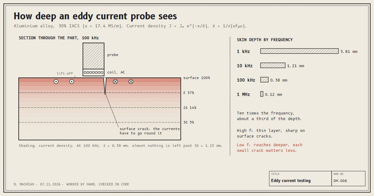
Ten times the frequency gives about a third of the depth, because δ goes with one over the square root of f, and √10 is 3.16.
One skin depth down, the current is at e⁻¹, 36.8 percent of its value at the surface. At two it is 13.5 percent, at three 5.0 percent. Past about three skin depths there is almost nothing left to be disturbed, so a flaw down there makes almost no signal.
Choosing the frequency
That table is the whole trade-off. A high frequency packs the current into a thin layer at the surface. A small surface crack then interrupts a large share of it, so the method is very sensitive to exactly the cracks that start at a surface, such as the ones growing from the edge of a fastener hole.
A low frequency reaches deeper, for a flaw under the surface or in a second layer of a joint, but spreads the current over more metal, so the same small crack disturbs a smaller share of it.
The material moves the numbers a long way. Copper at 100 percent IACS has a skin depth of 0.21 mm at 100 kHz. A titanium alloy at around 1 percent IACS has about 2.1 mm at the same frequency, ten times deeper, because the current has a harder time flowing. Steel is magnetic, μ is many times larger, and the skin depth collapses, which is why steel is usually tested at much lower frequencies.
What else moves the needle
The coil does not only feel cracks. It feels anything that changes the eddy currents, and most of the skill is telling those apart.
- Lift-off: the gap between the coil and the surface. A coat of paint or a tilted probe changes the signal far more than a small crack does.
- Conductivity: heat damage changes an aluminium alloy's conductivity, so the same instrument can check for it, or sort alloys.
- Edges and fasteners: the end of a plate interrupts the currents just as a crack does.
- Permeability, in magnetic materials, which swamps everything else.
The instrument shows the change as a point on an impedance plane, and lift-off and a crack move that point in different directions. That is how they are separated. The inspection is set up on a reference block of the same material with notches of known depth cut into it, so a signal on the real part is compared with a signal from a flaw of known size.
What it cannot see
The method needs a conductor, so it says little about most composites or paint. It sees badly past about three skin depths. And it needs the flaw to cut across the current.
That last one is the least obvious. The eddy currents flow in loops parallel to the surface. A crack running down into the part cuts straight across them. A separation lying flat, parallel to the surface, like a delamination, sits along the loops instead of across them, and barely disturbs them at all. For that you want a different test, which is the point the hangar kept making: there is no single test, and you choose it by what you are afraid of.
References
- Federal Aviation Administration. Advisory Circular 43.13-1B, Acceptable Methods, Techniques, and Practices: Aircraft Inspection and Repair. Chapter 5, Nondestructive Inspection.
- Federal Aviation Administration. Aviation Maintenance Technician Handbook: General (FAA-H-8083-30). Chapter on inspection concepts and techniques.